Task 2 FANUC I/O Unit Module Connection
1.2.1 FANUC PMC composition

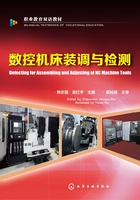
FANUC PMC consists of built-in PMC software,interface circuit,and peripheral devices(proximity switches,solenoid valves,pressure switches,etc.). The cable connecting the system and the subordinated I/O interface device is a high-speed serial cable called I/O Link,which is the dedicated I/O bus of FANUC. The I/O Link connection diagram is shown in Fig. 1-2-1.

Fig. 1-2-1 I/O Link
In addition,I/O Link can be used to connect βi series servo amplifier and servo motor which can be used as I/O Link axis. Through RS-232C or Ethernet,FANUC system can connect to computer,diagnose and edit PMC interface status,and modify the ladder online.
1.2.2 Common I/O unit module
There are many types of I/O unit modules in FANUC system. Table 1-2-1 shows frequently-used ones.
Table 1-2-1 Frequently-used ones

1.2.3 Connection of I/O unit module's input and output
For various types of I/O unit module of FANUC,input and output signal connections are basically the same. The following description is divided into input and output section. The most commonly used I/O unit module is taken as an example for your information.
When connecting the input and output signals,you must pay attention that there are two kinds of the input(local)/output connection. According to current flow direction,there are source input(local)/output and leakage input(local)/output. And using which type of connection is determined by common DICOM/DOCOM of the input/output. Common I/O unit module input and output signal connection types are shown in Table 1-2-2.
Table 1-2-2 Common I/O Unit Module Input/Output Signal Connection Type

I/O unit module,such as sub-line disk,can choose a group of 8-bit signal connected into a leakage or source type.
In principle,it is recommended to use sink input,which is +24 V switch input(active high)in order to avoid signal terminal ground malfunction.
For output of sub-line and other I/O unit module,source or leakage type output can be used in all conditions. Source output,that is,+24 V output,is recommended for safety. At the same time,in order to avoid short circuit,attention should be paid to polarity of freewheeling diode when connecting.
1.2.4 0i D series I/O unit module connection
0iD series I/O unit module is the most extensively used I/O unit module in CNC machine tool of FANUC system. Four 50-pin socket connections are used,which are CB104,CB105,CB106 and CB107. The input point has 96 points,and each 50-pin socket contains 24 input points which are divide into 3 bytes;the output point has 64,each 50-pin socket contains 16 output points which are divided into 2 bytes. 0i D series I/O unit module diagram and 450-pin socket specifications are shown in Table 1-2-3.
Table 1-2-3 Diagram of 0i D Series I/O Unit Modules and specifications of four 50-pin sockets

Two points need to be specially explained:
①The pin B01(+24V)of 50-pin socket(CB104,CB105,CB106,CB107)is used to input signals,which outputs DC 24V. Do not connect external 24V power to these pins.
②Each DOCOM is connected to the printed circuit board. If 50-pin socket is used to output signal(Y),make sure that DC 24V is input to the DOCOM of each 50-pin socket.
Table 1-2-3 shows that A14 pins of CB106 are defined,while other A14 pins are not defined. Leakage and source input can be chosen in CB106. Wiring method of 0i-D series I/O unit module is shown in Table 1-2-4.
Table 1-2-4 0i-D Series I/O Unit Module


In this case,a typical ZTXX30A CNC milling machine is taken as example. And the focus is I/O unit module selection and configuration methods.
In this case,the target machine tool is ZTXX30A CNC milling machine and its main specifications and parameters are shown in Table 1-2-5.
Table 1-2-5 Analysis of main specification and parameters


1.2.5 Training project
1. Training purpose
(1)To understand configuration of existing I/O unit module.
(2)To be able todemonstrate performances of I/O unit module configuration.
(3)To be familiar with the connection of I/O unit module.
2. Training project
Observe the configuration of training equipment and complete the form below(Table 1-2-6).
Table 1-2-6 Configuration of Training Equipment

3. Practice assessment
Observe the existing training equipment to find out which types of I/O unit modules it has,demonstrate the I/O unit module input/output points,and fill in the table 1-2-7:
Table 1-2-7 The I/O Units of Training Equipment
